

|
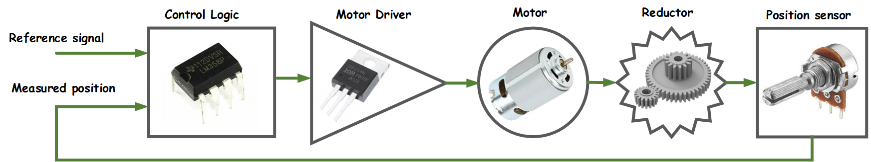
This project illustrates implementation of a custom servo motor, a motor that allows precise control of angular position based on gived reference (control) signal. This project is done by authors as a student project within the course of Sensors and actuators. Article entitled "Servos" posted by Norbert Heinz is used as reference [1]. Block diagram of implemented servo motor is shown below. Motor consists of control logic (regulator), motor driver, DC motor, mechanical reductor and rotary position sensor. Based on given reference signal (desired position) and measured position, via motor driver, control logic or regulator drives DC motor. Next, DC motor, via mechanical reductor, rotates position sensor to match given reference signal.
| Simple potentiometer is used as rotary position sensor. Motor driver is H-bridge, implemented using complementary N-channel (IRF540N) and P-channel (IRF9540N) MOSFET transistors. MOSFET transistor are switched via totem-pole stage implemented using PN2222A transitors. 4N25 optocouplers are used for bridge isolation from control logic. Regulator is implemented as simple ON/OFF regulator using OPA2340PA rail-to-rail dual operational amplifier. Operational amplifiers are used as voltage comparators within regulator. Regulator has two outputs (OUT1 and OUT2) which are directly connected to H-bridge inputs. Servo motor is implemented in such way that reference or control signal can be either analog (voltage) or digital (PWM). Analog or digital mode of operation can be selected via board jumper. If analog mode is used, reference signal is directly passed to regulator for comparison with analog signal from position potentiometer. On the other hand, if digital mode is used, digital reference signal in form of PWM is first converted to analog and then passed to regulator for comparison. Conversion is achieved using low pass RC filter (average value extraction) and OPA2340PA amplifier stage. In demo video below PWM signal is generated using Servo tester. Required PWM signal corresponds to typical PWM signal used with popular RC hobby servo motor. Simulation of PWM to analog circuit made using MicroCap is provided below. | 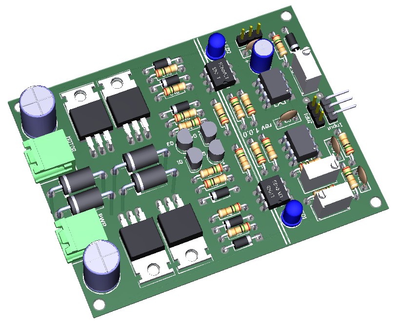 |
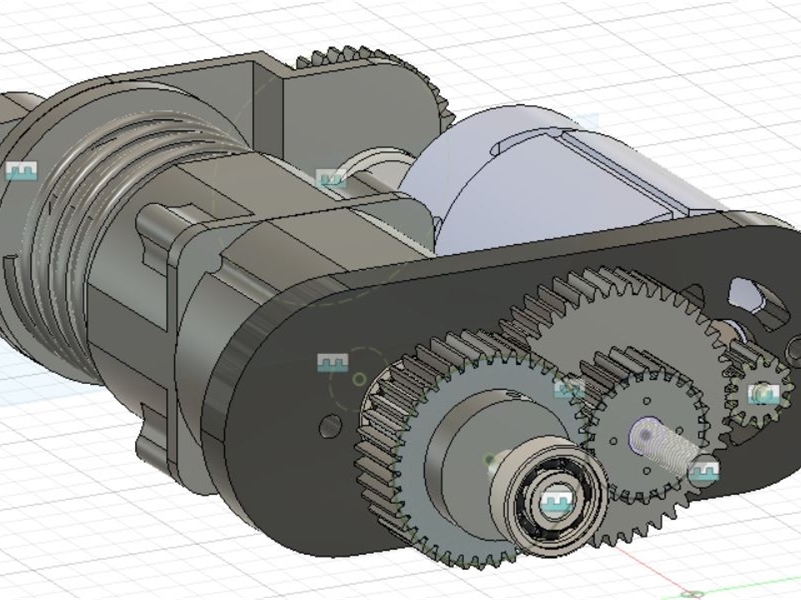
Two servo models are provided below. Model V1 is simpler, parametic model, designed using OpenSCAD. It is design fror gearmotors (such as this or this) and it can be easily adapted for different DC motors. Motor is coupled to sensing potentiometer via simple 3D printed spur gears (gear ration can be adjusted in OpenSCAD).


Model V2 is a bit more complex, but also more powerful. This servo motor is implemented using DC motor and planetary reductor extracted from an old cordless drill. Via 3D printed gears DC motor is coupled with planetary reductor upon which output shaft is located. Rotary position sensor (potentiometer) is coupled with planetary reductor on the output side also using 3D printed gears. Such design enables high torque servo motor.
References:
[1] Norbert Heinz, “Servos”.
PROJECT FILES&DOCS:
|
- Servo motor schematic: pdf |
IMAGE GALLERY:


VIDEO GALLERY:
Joomla Extensions- Details
- Category: Project Base
- Last Updated: 01 July 2022
- Hits: 10681