

|
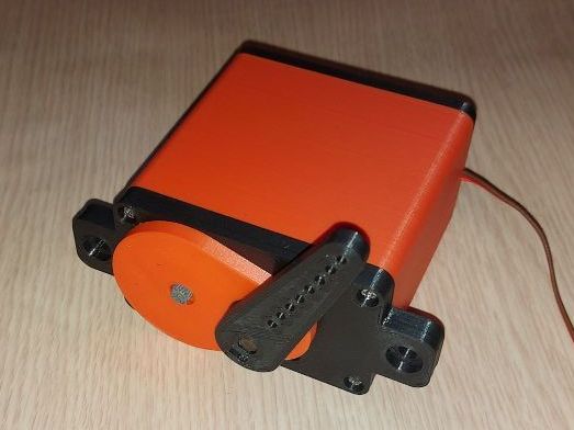
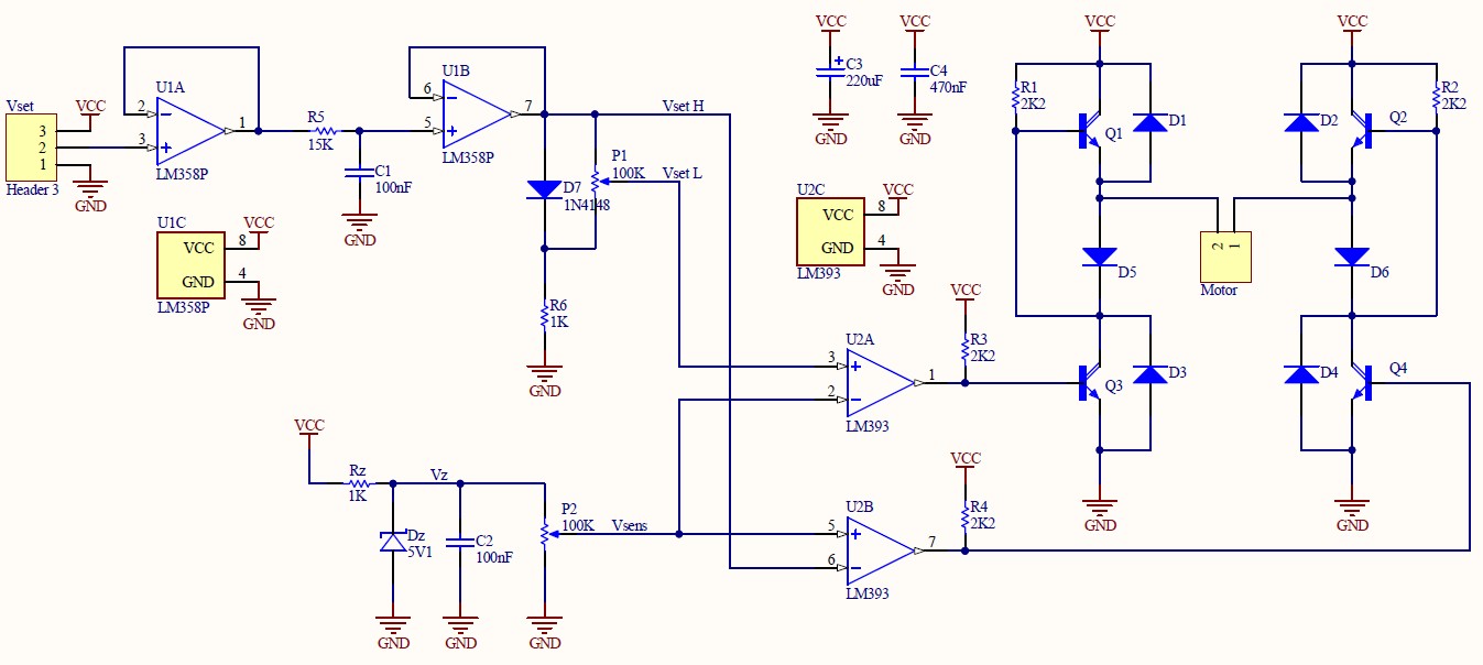
This project illustrates implementation of a simple, custom built, educational, servo motor. Project was a student assignment within course of Application of Sensors and Actuators. Goal was to design and demonstrate servo motor principle. Implemented motor consists of a DC motor with reductor, linear potentiometer as rotary position sensor, 3D printed casing and custom built electronics. Schematic of the electronic part of the motor is given in figure below. Simple ON-OFF regulator is used to control status of the DC motor via H-bridge driver. Motor can be easily controlled with microcontroller such as Arduino bord using PWM signal (analogWrite in case of Arduino).
|
Input PWM signal is passed through RC filter (R5, C1) and converted to analog signal. This signal is compared to analog signal obtained from sensing potentiometer (P2) using two comparators (LM393). Zener diode 5V1 is used to provide stabilized power to sensing potentiometer. Comparators outputs are directly connected to H-bridge, controlling motor status. H-bridge is implemented using 4 npn Darlington transistors BD 681 and 6 diodes 1N4007. If signal from the sensing potentiometer (Vsens) is between VsetL and VsetH both comparator outputs are low and motor is inactive, holding current position. Otherwise, if for instance is Vsens<VsetL, then comparator U2A output is high, motor is turned on and via gearbox spins the sensing potentiometer until Vsens becomes larger than VsetL, reaching the holding position. Similar procedure repeats if Vsens>VsetH, motor is turned on and via gearbox spins the sensing potentiometer, now in opposite direction (comparator U2B output is high), until Vsens becomes lower than VsetH. Difference between VsetL and VsetH can be adjusted via potentiometer P1. If VsetL and VsetH are adjusted to be equal than servo motor operation would be unstable at holding position. Larger the difference between two voltages is, more stable operation is achieved, but also motor positioning resolution is decreased. Therefore, voltage difference between VsetH and VsetL is set to around 100mV. Servo case is to made to resemble standard RC servo motors. It is designed using OpenSCAD software and it is made to be parametric so it can be easily adapted to different motors, rotary sensors and gear ratio. PROJECT FILES&DOCS: - Servo motor schematic: pdf |
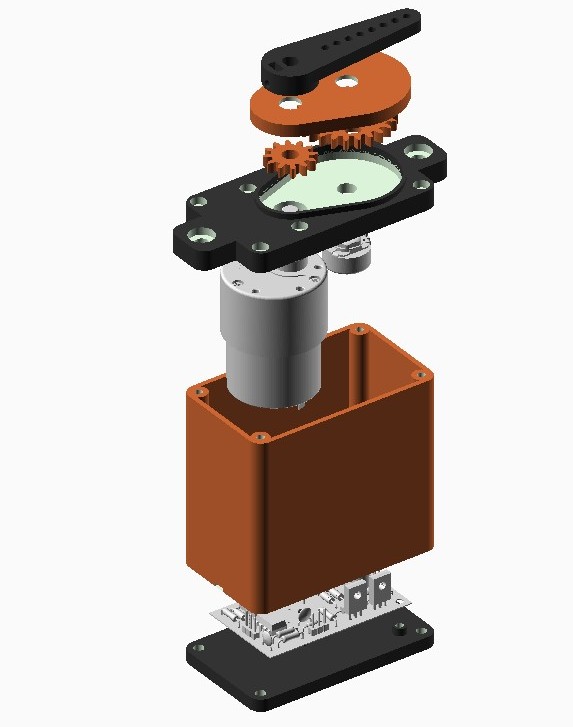 |
IMAGE GALLERY:


VIDEO GALLERY:
Joomla Extensions- Details
- Category: Project Base
- Last Updated: 17 August 2023
- Hits: 4214