

|
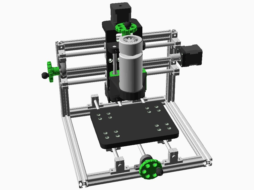
This project presents a DIY CNC machine that was master thesis project of our students. Machine is built using 20x20 aluminium extrusion profiles and commonly available mechanical elements such as threaded rods (T8), linear rods with supports (SK8 for y and SK10 for x axis) and bearing platforms (SC8UU and SC10UU) and motor coupling (5/8 mm), while other specific mechanical elemets are 3D printed (z axis mount, motor mounts for x and y axis and work bed). Axis actuation is achieved using standard NEMA17 motors, while as spindle 300W, 48V, 12000 rpm DC motor is used. CNC electronis is based on Arduino Uno CNC shield and uses Atmega328 mcu and A4988 stepper motor controler, all integrated into single board (it shares sames pinout as Arduino Uno and its CNC shield). Highly optimized, open source GRBL fimware is used for the CNC motion control. GRBL fimware, written in C language, is high performance, low cost alternative to parallel-port-based motion control for CNC milling. As input it accepts standard g-code commands. 12V, 150 W switcihg power supplay is used for powering the CNC. For spindle supplay additional DC-DC step up converter is used in order to achieve full spindle speed of 12000 rmps (at 48V). In order to avoid power supplay fail due to current surge (motor strating current) current limiting on DC-DC step up converter and motor soft start (generated via g-code) are used. CNC schematic, PCB, GRBL firmware config and spinde soft start g-code are provided below.
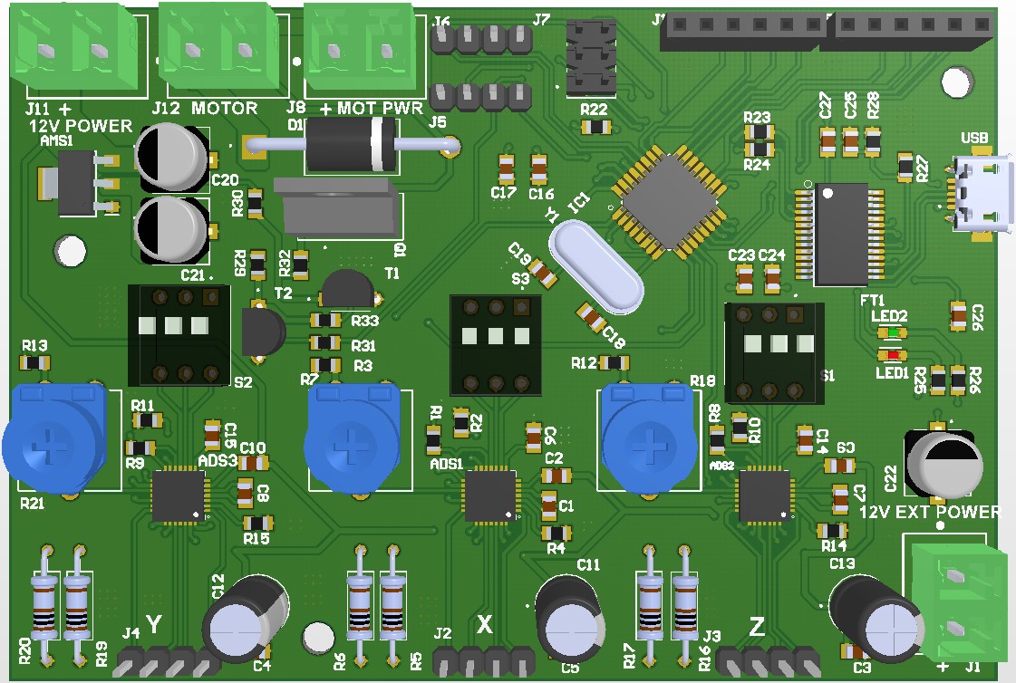
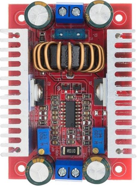
Custom designed CNC board and DC-DC step-up converter
CNC model is built using OpenSCAD CAD design software. Model is parametric and can be adjusting and adapted accordingly.
|
In demo below this CNC machine is used for PCB milling. FlatCam software is used to generate CNC job g-code, while Candle software is used for machine control (passing generated g-code). PCB milling in demo is done in 3 steps. First step is isolation milling which was performed using 20°/0.2 mm V shaped cutter tool. G-code for isolation milling is generated using FlatCam based on PCB’s bottom layer gerber file (*.GBL, check image gallery). Second step was holes drilling using g-code generated based on PCB’s NC drill txt file. Finaly, based on keep-out layer gerber file (*.GKO) board cutout is performed. Holes drilling was performed using standard 1.0 mm PCB microdrill bit, while for cutout 1.0 mm corn cutter tool is used. Prior to milling, drilling and cutting it is recommended to map the surface of the PCB (supported by Candle software) in order to achieve the best results. Most critical step is isolation milling due to very thin coper layer and it requires a bit of experimentation (cutting depth, speed, etc.) in order to achieve satisfactory results. PROJECT FILES&DOCS: - CNC Board schematic: pdf |
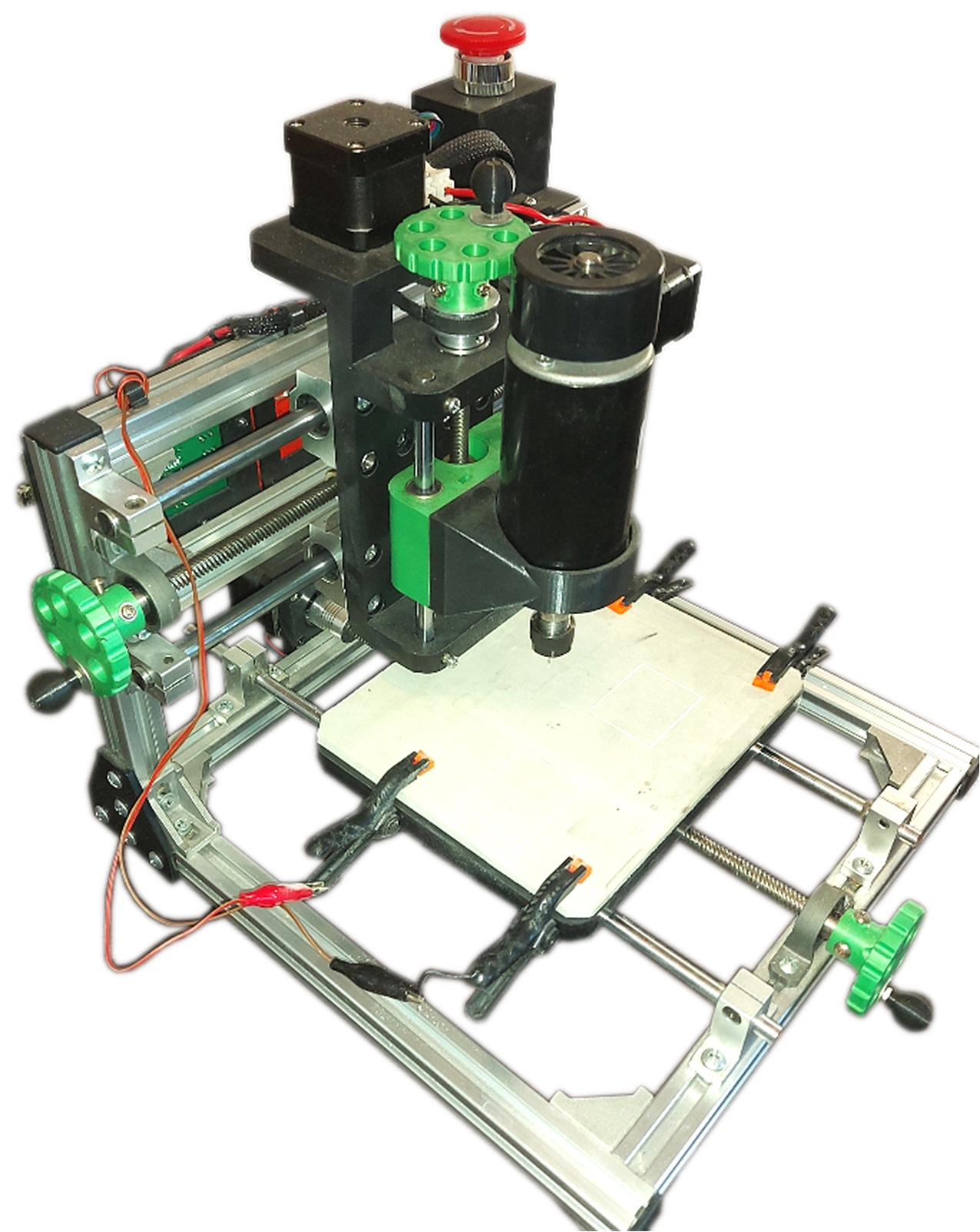 |
IMAGE GALLERY:


VIDEO GALLERY:
Joomla Extensions- Details
- Category: Project Base
- Last Updated: 08 April 2024
- Hits: 4438